21 April 2017

Understanding Basic Tube Amplification

AC Voltages & DC Voltages


There are two type of electricity in tube amplifier circuit, AC voltage and DC voltage. AC is alternating current at a particular frequency, basically is a sine wave  or a combined sine wave like audio signal. DC is just  a static voltage like a 9v battery or an audio power supply 280v.

In tube amplifier, AC voltage can really be DC voltage that changes value, suppose you measure 280v multiple time in a few second, you will get 290v, 280v and 270v. This wound be considered ac signal which to have a 20v changes.

When we put an audio signal into our circuit which is in Dc voltage.We actually modulate our AC signal with DC voltage which then will be amplified to create a new AC signal which is again sitting on the DC voltage. Then we use a coupling capacitor to filter out the DC voltage. What''s left is the 20v audio signal oscillating around zero voltage.

So, the first thing to check in a tube amplifier are the DC voltages., even before we start listen to any tube amplifier.

24 March 2017

Tube Pins

Here at below we can see a ECC81 or 12AT7 tube pins

12AT7 has two amplification section in it. Start from pin 1, that is the anode/plate of the first device. Pin 2 is the grid where the audio signal goes into and pin 3 is the cathode. Together it form one amplification. Another section will be pin 6, 7 and 8.

Then you will see pin 4,5 & 9. These are filament pin which used to boil the electron at the cathode. It can be connected for either 6.3v in parallel (Pin 4&5 with 9) or 12.6v by serial (pin 4 with 5) ac or dc, sound funny...lol


El34 is a power pentode tube. Unlike triode, it have 3 grid(g1, g2 & g3), a anode(a) and a cathode(k). Pin 2 and 7 will be the filament. This tube only have 8 pins, mean that it use 8 pin noval socket.

13 March 2017

Capacitor

Capacitors is a passive electrical component consist of two equal but opposite charge plates, separated by a dielectric. It is use to store electrical energy temporarily in a electric field.


There are different types of capacitors use in tube amplifier circuit,

Polarize capacitor likes electrolytic capacitor which have positive(+) and negative(-) must be installed correctly if not it will behave like a dead short and blow. The negative (-) lead should be the one grounded.


Non-polarize used as your coupling capacitor, they are banded  to show which lead is outside the foil which can be serve as a shield against Electromagnetic interference. The banded lead should go to the proceeding plate. If used as a bypass capacitor the banded lead should go to the HT B+.


Typical value you will see in a tube amplifier circuit is

0.22uf = 0.22 x 1/1000000 = 0.00000022 Farad
470uf = 470 x 1/1000000 = 0.000470 Farad
47uf = 47 x 1/000000 = 0.000047 Farad

Capacitance are measure with Farad, since it was too small, we measure it in mili(mf), micro(uf), nano(nf) and pico(pf) Farad

Voltage rating is very importance in capacitance. It directly related to his dielectric which mean how many voltage it can withstand before shorted and blow. Always use the right voltage rating. There are different material used as dielectric, likes paper, polypropylene film, polyester film, mylar...etc. Each of it have it own pros and cons.

07 March 2017

Resistor

Resistor is a passive two terminal electric components that implements electrical resistance as a circuit element. The current through a resistor is represent by ohm's law; V=IR


Resistor has a color code on it with each color representing a number between 0 to 9. You can learn to understand the value of a resistor by reading the color.


The simplest way is by measure the value at your resister using multimeter. Set it to Ohm and start measure on each side of the resistor.


Typical value you will see in a tube amplifier circuit is

100K = 100 x 1000 = 100000 ohm
100R = 100 ohm
1K8 = 1.8 x 1000 = 1800 ohm
1M2 = 1.2 x 1000000 = 1200000 ohm

Resistor come on difference wattages. We usually use 1/2W, 1W, 2W, 5W, 10W. Even thought it can with stand 10W, it does not mean it won't be hot.

05 March 2017

Hardware & Tools

Beside electronic components you will need to prepare some hardware before you start.


Color coded cable, Shielded cable, Bolt and Nuts,

These are the tools you mainly use in building your tube amplifier likes screw driver, soldering iron, solder lead, Multimeter and long nose plier.


03 March 2017

Reading Schematic

Let's have a look at the schematic


High Tension(HT) Power Supply

This is the power supply circuit. Boxed with blue box is the Main Transformer. On the left side, It was connected to the wall socket (In Malaysia 240v 50Hz) with SW-1 on/off switch and fuse. On the right side, at the top winding is 5vac which connected to rectifier filament. The second winding is 400-0-400vac, connected to the 5V4G rectifier tube which form a full wave rectification. The last winding 6.3vac connected to driver and power tube (6SJ7, 6N7, 6AS7G) filaments.

The second section which boxed with yellow is the LC filter, they are 7H 140mA choke and 40uf 450v capacitor for smoothing the voltage.The first resister after the filter is the 30K 10w bleeding resistor. It use to drain the voltage after the amplifier was switched off. The last one will be a RC filter used to filter and reduce the voltage for the driver.


Amplifier Circuit

At here, It is a long story to explain how it work. I will tell you what is the name of the components in a tube amplifier so if there a problem you can always discuss in the forum.

At the input, this is where the signal (audio) was injected to the amplifier. Follow by a 500K volume pot (variable resister). Usually after the volume pot we put a grid leak resistor around 470K ohm to 1M ohm. In this case, the volume will act as grid leak resistor. And after the grid leak resistor some circuit will have another resistor in series with the screen call grid stopper resister.

On top of 6SJ7 is the 100K plate resister. The one which connected at the 6SJ7 cathode is the 5K6 cathode bias resister. Feedback resister 270K also connected to the 6SJ7 cathode. Coupling capacitor are those with 100nf and 2uf, no voltage are show, I will make assumption from the power of the main transformer which is around 400v.

The 100uf at the 6N7 and 40uf at 6AS7G are cathode bias capacitor, no voltage are show either. The easy way is to refer to other schematic who use the same tube or just put in a 100v capacitor. The real way is to measure the cathode bias voltage and put a capacitor which is higher then the cathode bias voltage.

This circuit use two transformer, inter-stage with 10K to 80K ohm impedance and a push-pull output transformer of 3K to 8 ohm impedance. 8 ohm is not show on the circuit because it is flexible, depend of what speaker you want to use. It can be 4 ohm, 6 ohm, 8 ohm or 16 ohm.

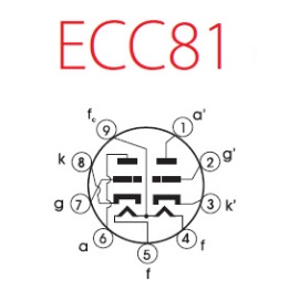
B+1 and B+2 are where you get your power supply from the HT Power circuit. The small triangle thing below the circuit is the grounding. The amplifier circuit only show one channel, which mean you have to repeat the circuit for the other channel. Basically we don`t repeat the Power circuit unless you want to build two mono amp. The tube pins connection also not shown. So you have to refer to the tube datasheet for pins connection.


27 February 2017

What should I plan?

What should I plan if I haven`t build  a Tube Amp before?

At this stage, freedom of choice, freedom of choosing your circuit and components are unlimited. As an engineer, I will take what is needed and reliable. There are many suggestion and comment on internet.


Schematic

Tube amp circuit always associate with the power tube that you want to use, Single Ended or Double Ended (Push-Pull). You may not want a schematic which is still under discussion. Pick those which have been build before. Simple is better....lol


Chassis Layout

In Tube Amp, they use large components which must be place relative near to one another. So that the connecting wires between each components are as short as possible and do not interfere with each other. Choose one that fit all your components and they should be some space for your soldering gun. Larger is better (^_^).


Major items to be positioned, it is better to know the dimension before purchase.

Main Transformer
Output Transformer
Rectifier valve
Filter Capacitor
Power Tube, Driver Tube
Amplifier Circuitry